
- DC MOTOR WITH PWM AVR CODEVISION AVR HOW TO
- DC MOTOR WITH PWM AVR CODEVISION AVR SOFTWARE
- DC MOTOR WITH PWM AVR CODEVISION AVR CODE
He used the eXtreme Burner for burning the code. He has used the low cost 28 pin AVR Development Board and the USBasp AVR Programmer by eXtreme Electronics. The video is made by Lavin Khandelwal for ma圎mbedded. This is a simple demonstration of controlling two DC motors using a single L293D IC and a microcontroller.
DC MOTOR WITH PWM AVR CODEVISION AVR CODE
The code can also be found on pastebin and in the code gallery.Īfter burning the code into your MCU, you will find that the motors rotate in clockwise direction for 0.5s and counter-clockwise direction for 0.5s. If you are new to AVR Studio 5, you can read this post to get started with it. Amplitude: 0-3V at 9V DC Input I will try to do better with an Arduino or. Now open up AVR Studio 5, type the following code and build it. I ported his C version to the AVR and was able to achieve a nice digital sine. All that happens is that the ESC generates beep sounds signifying no signal. I dont have any equipment to actually see what the generated PWM signals are actually.
DC MOTOR WITH PWM AVR CODEVISION AVR SOFTWARE
However, the software generated technique doesnt work.

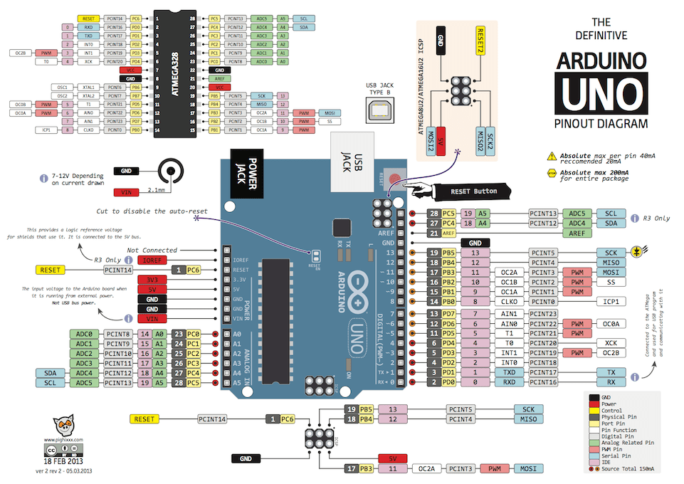
Assuming ATMEGA32, let us connect L293D across PORTC pins (PC0…PC3) as shown in the diagram below. With the hardware generated PWM using the timer my ESC is able to run the brushless DC motor. Now let’s generate control signals from the AVR MCU and feed them to the inputs of L293D. Most DC motors are normally very easy to reverse.
DC MOTOR WITH PWM AVR CODEVISION AVR HOW TO
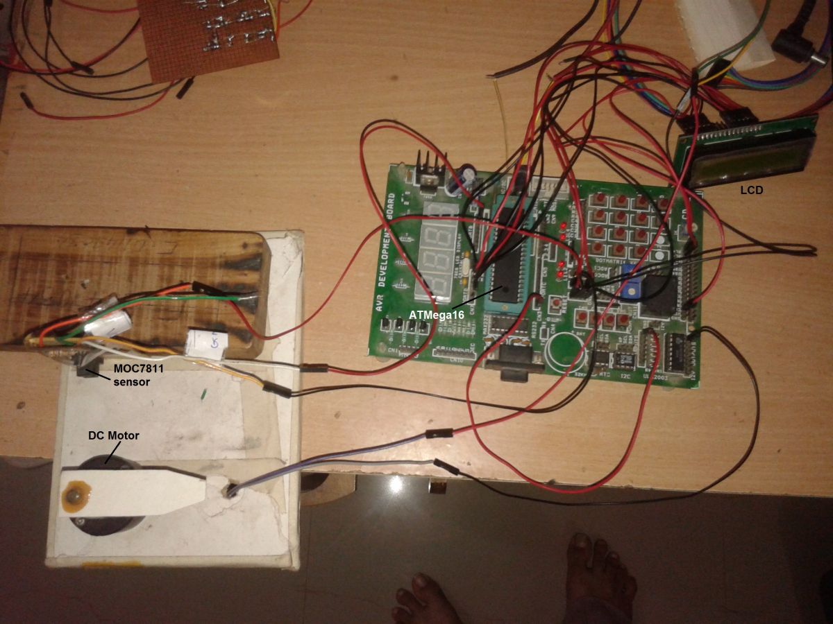
In this post we will discuss how to control DC Motors (geared or gearless) using a MCU. Enabling both pins at the same time will drain your battery unnecessarily. In the field of robotics, we use different types of motors DC motors (mostly geared), servo motors, stepper motors, etc. It increases pulse width from 10 to 99 and measures DC motor RPM and displays pulse width as well as RPS (revolution per second) on LCD.

The project is built using AVR micro controller ATMega16. Suppose if you need to control only one motor at a time, you need to enable that particular EN pin. It generates PWM to vary speed of DC motor and at the same time it continuously measures RPM of it.


 0 kommentar(er)
